External interrupt / event controllerEXTI Chapter
EXTI Datasheet
Interrupt mask, edge trigger selection, pending flag and line-to-pin routing
EXTI6/Hall User Description: trainer route and visible behavior
- Document ID
- EXTI-DS001
- Revision
- Rev 1.2
- Base address
- 0x40010400
- Scope
- Line 6 centered EXTI subset
EXTI does not replace the GPIO input path. It observes the selected GPIO line, detects configured signal edges and generates an
interrupt or event request. GPIO input configuration and EXTI edge configuration are therefore programmed separately.
Contents
- General description
- Main features
- EXTI architecture
- Register map and reset values
- Register descriptions
- Student register guide and code examples
1 General description
The external interrupt / event controller generates interrupt requests or event pulses from selected GPIO input transitions.
Each EXTI line may be masked or unmasked, and rising edge or falling edge detection can be enabled independently.
When a configured trigger reaches an interrupt branch that is unmasked in EXTI_IMR,
the corresponding pending bit is set until cleared by software. An event-only branch enabled through
EXTI_EMR produces an event pulse without setting EXTI_PR.
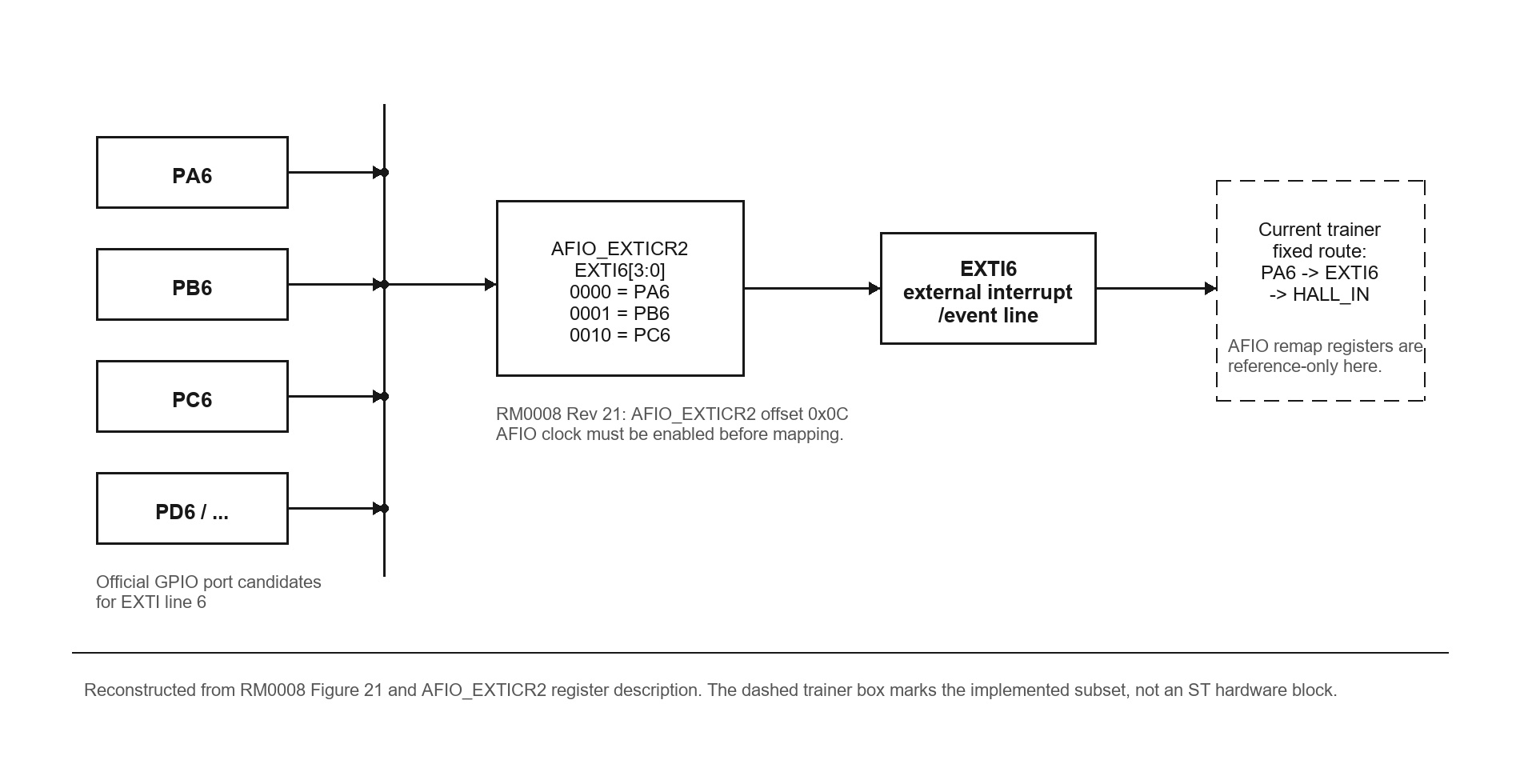
In the implemented subset used by the site, line 6 is the primary line of interest. On the real STM32F103, EXTI line 6 can be
sourced from PA6, PB6, PC6, and the matching line-6 pad
on other ports through AFIO_EXTICR2. The Trainer now exposes
AFIO_EXTICR2.EXTI6[3:0]; value 0000 selects the implemented
PA6 -> EXTI6 -> HALL_IN source. Other port-selector values remain reference/storage behavior because no PB6/PC6 Hall pulse source is modeled.
2 Main features
- Maskable interrupt line
- Independent rising and falling edge trigger definition in the official register model
- Sticky pending flag cleared by write-1
- GPIO input and EXTI configuration separated into different register groups
3 EXTI architecture
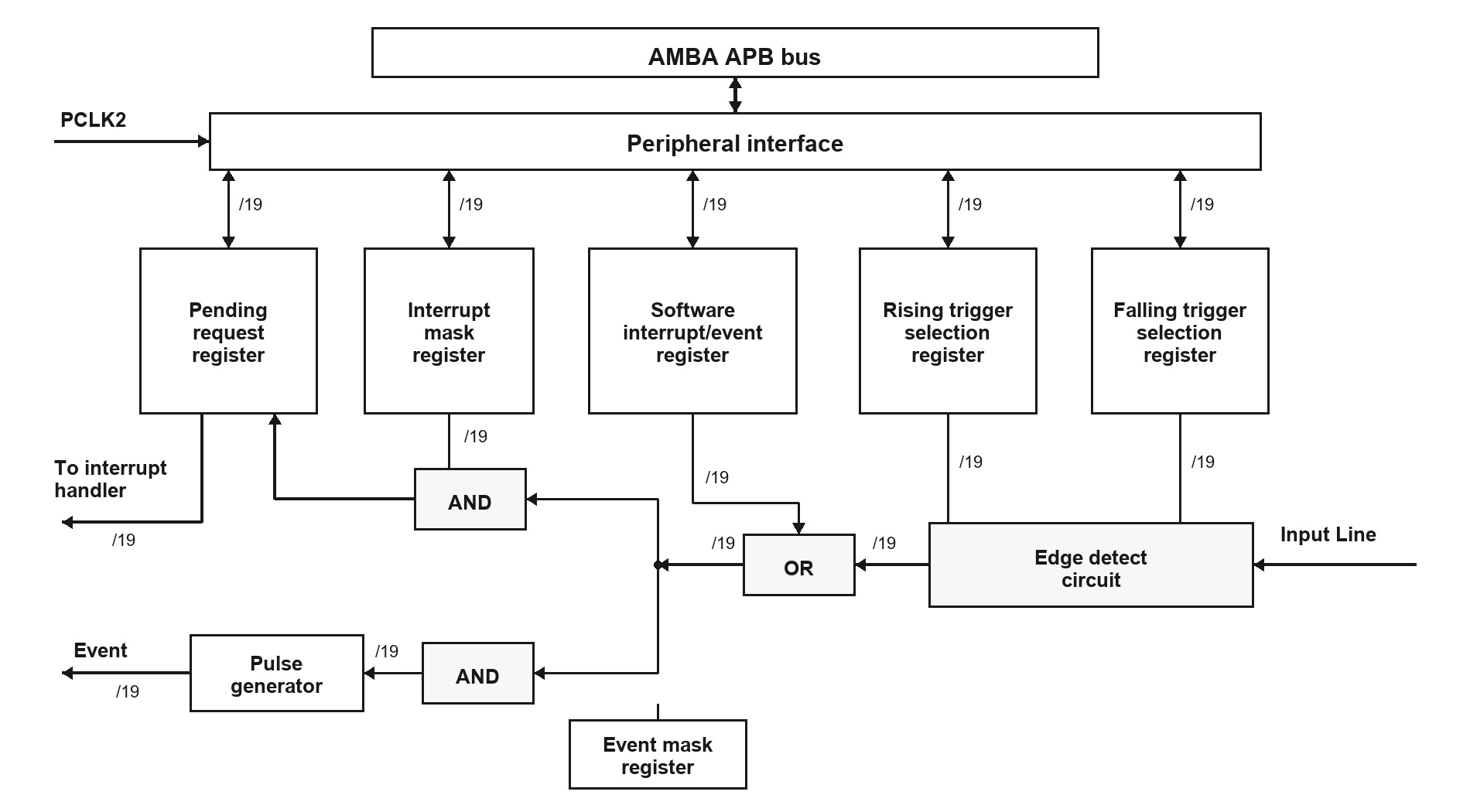
Read Figure 2 as Input Line -> edge detect / SWIER request -> interrupt and event branches. A selected edge creates one request for the transition; holding the input HIGH does not create repeated requests. The trainer-relevant interrupt path is Hall sensor to PA6 to EXTI6 to the IMR.MR6 interrupt gate to the PR.PR6 pending latch to ISR. In the official event path, the edge/software-trigger result branches through EMR.MR6 and the pulse generator without passing through either IMR or the pending latch. The event pulse does not feed back into PR. If event and interrupt branches are both enabled, the same trigger sets PR through the independently enabled IMR branch, not through the event pulse. Falling-edge configuration remains exposed for reference-manual shape, but the current lab flow uses rising Hall pulses only. Event mode and software interrupt injection are official RM0008 reference paths; the current trainer header/MMIO map does not expose EXTI_EMR or EXTI_SWIER as executable registers.
Figure 20 uses /19 to mark 19 parallel lanes, EXTI0 through EXTI18. Connectivity-line devices add Ethernet-wakeup EXTI19; bit 19 is reserved on other devices. CPU register accesses travel through the AMBA APB bus and the EXTI peripheral interface, which is clocked by PCLK2, but RCC has no separate EXTIEN bit. AFIOEN is required to program AFIO_EXTICRx, and the owning GPIO port clock is required to configure the GPIO input path.
| EXTI line |
Official source-selection field |
Official source values |
Current trainer route |
| Line 6 |
AFIO_EXTICR2[11:8] (EXTI6[3:0]) |
0000 = PA6, 0001 = PB6, 0010 = PC6, up to implemented GPIO ports; 0111-1111 = Reserved, 사용하지 않음. |
EXTI6=0000 is supported and connects PA6 / HALL_IN. Other selector values are readable/writable but have no modeled Hall pulse source. |
GPIO EXTI mapping follows the pin index: Px0 maps to EXTI0 through Px15 maps to EXTI15. For each EXTI line, AFIO_EXTICRx selects exactly one available port source at a time; EXTI6 cannot receive PA6, PB6 and PC6 simultaneously. The Trainer executes the motor Hall route only when AFIO_EXTICR2.EXTI6=0000 selects PA6 / HALL_IN.
Line number and pin name are separate: MR6, TR6, and PR6
identify EXTI line 6; they do not identify GPIO port A by themselves.
PA6 is the selected source only because AFIO_EXTICR2.EXTI6[3:0] = 0000.
The current Trainer exposes that field as an executable register and requires value 0000 for the modeled PA6 Hall source.
3.1 PA6 GPIO nibble before EXTI6
| Pin / interrupt line | Register | Field / bit | Official value meaning | Current trainer result |
|---|
| PA6 / EXTI6 | GPIOA_CRL | CNF6[27:26] / MODE6[25:24] | Figure 1 receives a digital input from PA6 before EXTI line 6 can see an edge. The owning nibble is GPIOA_CRL[27:24]. 0x4 (0100) means CNF6=01, MODE6=00, floating digital input; 0x8 (1000) means pull-up/down input and uses ODR6 for pull direction. | The Trainer uses the PA6 / HALL_IN board signal, checks that PA6 is configured as an input, and then requires AFIOEN, IOPAEN, AFIO_EXTICR2.EXTI6=0000, EXTI_IMR.MR6, and EXTI_RTSR.TR6. |
The field write is GPIOA->CRL = (GPIOA->CRL & ~(0xFu << 24)) | (0x4u << 24). See the GPIO Register Datasheet for the complete nibble table.
The common Hall adapter is a 3.3 V open-collector signal with an external pull-up to the MCU I/O rail, so PA6 observes approximately LOW/3.3 V. DS5319 Rev 20 does not mark PA6 as an FT pin; never pull the Hall output up to 5 V or connect an unconditioned 5 V push-pull output directly. Hall transitions-per-revolution and pulses-per-stroke are Trainer plant assumptions because no Hall vendor datasheet is selected.
4 Register map and reset values
| Offset | Absolute address | Register | Reset value | Official purpose / trainer boundary | Trainer 지원 여부 |
|---|
| 0x00 | 0x40010400 | EXTI_IMR | 0x00000000 | Interrupt mask register. The trainer uses MR6 as the Hall interrupt gate. | 지원됨 |
| 0x04 | 0x40010404 | EXTI_EMR | 0x00000000 | Event mask register. This official event branch is documented but not exposed by the current header/MMIO contract. | 미지원 |
| 0x08 | 0x40010408 | EXTI_RTSR | 0x00000000 | Rising trigger selection register. The trainer uses TR6 for Hall rising-edge counting. | 지원됨 |
| 0x0C | 0x4001040C | EXTI_FTSR | 0x00000000 | Falling trigger selection register. The register is stored and visible, but the current Hall counter is rising-edge driven. | 미지원 |
| 0x10 | 0x40010410 | EXTI_SWIER | 0x00000000 | Software interrupt event register. This official software-trigger branch is documented but not exposed by the current header/MMIO contract. | 미지원 |
| 0x14 | 0x40010414 | EXTI_PR | 0x00000000 | Pending register. The trainer sets PR6 on modeled Hall rising edge and clears it with write-1. | 지원됨 |
RM0008 contains a reset-notation discrepancy for EXTI_PR: Table 64 lists
PR[19:0] as zero in the register map, while Section 10.3.6 labels the detailed
register reset value Undefined. The map row above preserves Table 64; the detailed
description below preserves Section 10.3.6. Software should clear any handled pending bit with write-1-to-clear
rather than relying on an assumed initial PR value. This official discrepancy is separate from the current trainer:
the trainer deterministically initializes EXTI_PR to 0x00000000
on reset.
RM0008 requires every EXTI peripheral register to be accessed as a 32-bit word. Across all six registers
(EXTI_IMR, EXTI_EMR, EXTI_RTSR,
EXTI_FTSR, EXTI_SWIER, and EXTI_PR),
bit 19 is implemented on connectivity-line devices only and is reserved on the other STM32F103 device groups.
The offsets in this table are the official RM0008 EXTI offsets. The trainer's C pointer struct preserves those offsets: unsupported EXTI_EMR and EXTI_SWIER slots are reserved at 0x04 and 0x10, so EXTI->RTSR, EXTI->FTSR, and EXTI->PR stay aligned with the official layout. Symbolic constants preserve the same official addresses for read_reg() / write_reg() examples.
5 Register descriptions
5.1 Interrupt mask register (EXTI_IMR)
Address offset: 0x00
Reset value: 0x00000000
| Bit | Name | Access / values | Meaning | Current trainer register-value behavior |
|---|
| 31:20 | Reserved | - | Bits 31:20: Reserved; keep at reset value 0. | - |
| 19:0 | MRx | rw; 0 = masked, 1 = unmasked | Bits 19:0 MRx (rw): Figure 2 uses this as the interrupt branch gate. 0 masks the interrupt request from line x; 1 unmasks it. If EXTI_IMR.MR6 = 0, a selected trigger does not pass through the line-6 interrupt branch and therefore does not set PR.PR6 through that branch. Bit 19 is connectivity-line-only. | MR6 gates Hall interrupt handling in the current trainer. |
5.2 Event mask register (EXTI_EMR)
Address offset: 0x04
Reset value: 0x00000000
| Bit | Name | Access / values | Meaning | Current trainer register-value behavior |
|---|
| 31:20 | Reserved | - | Bits 31:20: Reserved; keep at reset value 0. | - |
| 19:0 | MRx | rw; 0 = masked, 1 = unmasked | Figure 2 uses this as the event branch gate. 0 masks the event request from line x; 1 lets the selected edge generate an event pulse. The event branch does not use the PR pending latch. Bit 19 is connectivity-line-only. | Reference-only; EXTI_EMR is not exposed by the current trainer header/MMIO contract. |
5.3 Rising trigger selection register (EXTI_RTSR)
Address offset: 0x08
Reset value: 0x00000000
| Bit | Name | Access / values | Meaning | Current trainer register-value behavior |
|---|
| 31:20 | Reserved | - | Bits 31:20: Reserved; keep at reset value 0. | - |
| 19:0 | TRx | rw; 0 = disabled, 1 = rising trigger enabled | Bits 19:0 TRx (rw): Figure 2 uses this block to decide whether a low-to-high edge is accepted. 0 disables the rising trigger for both event and interrupt paths; 1 enables it. Rising and falling triggers may both be enabled. RM0008 notes that an edge arriving while this register is being written may not set the pending bit. Bit 19 is used on connectivity-line devices only and is reserved otherwise. | TR6 must be set for the current Hall rising-edge count route. |
5.4 Falling trigger selection register (EXTI_FTSR)
Address offset: 0x0C
Reset value: 0x00000000
| Bit | Name | Access / values | Meaning | Current trainer register-value behavior |
|---|
| 31:20 | Reserved | - | Bits 31:20: Reserved; keep at reset value 0. | - |
| 19:0 | TRx | rw; 0 = disabled, 1 = falling trigger enabled | Bits 19:0 TRx (rw): Figure 2 uses this block to decide whether a high-to-low edge is accepted. 0 disables the falling trigger for both event and interrupt paths; 1 enables it. RM0008 gives the same write-time edge caution as for RTSR. Bit 19 is used on connectivity-line devices only and is reserved otherwise. | TR6 is stored and visible, but the current trainer Hall counter uses rising edges only. |
5.5 Software interrupt event register (EXTI_SWIER)
Address offset: 0x10
Reset value: 0x00000000
| Bit | Name | Access / values | Meaning | Current trainer register-value behavior |
|---|
| 31:20 | Reserved | - | Bits 31:20: Reserved; keep at reset value 0. | - |
| 19:0 | SWIERx | rw; 0 = no software request, 1 = request line x | Figure 2 uses this block as the software-trigger input. Writing 0 makes no new request. Writing 1 to a bit that was 0 requests the same line through the enabled interrupt/event masks; for an interrupt-enabled line, RM0008 sets the matching PRx pending bit. The bit clears when software clears PRx. Bit 19 is connectivity-line-only. | Reference-only; EXTI_SWIER is not exposed by the current trainer header/MMIO contract. |
5.6 Pending register (EXTI_PR)
Address offset: 0x14
Reset value: Undefined
| Bit | Name | Access / values | Meaning | Current trainer register-value behavior |
|---|
| 31:20 | Reserved | - | Bits 31:20: Reserved; keep at reset value 0. | - |
| 19:0 | PRx | rc_w1; 0 = no pending request, 1 = pending request / write 1 clears | Bits 19:0 PRx (rc_w1): Figure 2 shows this as the sticky pending latch before handler service. 0 means no selected trigger request occurred. 1 means one occurred and is waiting for software service. Software clears the pending condition by writing 1 to the corresponding bit position; writing 0 has no effect. Bit 19 is connectivity-line-only. | PR6 is the current line-6 pending/clear field; the trainer initializes EXTI_PR to 0 and clears PR6 on write-1. |
5.7 Related AFIO source-selection register (AFIO_EXTICR2)
Address offset in AFIO block: 0x0C Reset value: 0x00000000
| Field | Name | Access / values | Meaning | Current trainer register-value behavior |
|---|
| 11:8 | EXTI6[3:0] | rw; 0000 = PA6, 0001 = PB6, 0010 = PC6, 0011 = PD6, 0100 = PE6, 0101 = PF6, 0110 = PG6, 0111-1111 = Reserved, 사용하지 않음 | Figure 1 uses this selector to choose which GPIO line-6 pad feeds EXTI line 6 in the full STM32F103 source-selection model. | Supported field behavior. 0000 executes the PA6 / HALL_IN route; other values are retained/read but their GPIO pulse sources are not modeled. |
6 Student register guide and code examples
| Current code / value | Datasheet field interpreted as | Trainer에서 확인 |
|---|
| RCC->APB2ENR |= (1u << 0) | (1u << 2) | RCC_APB2ENR.AFIOEN[0] and IOPAEN[2] open the AFIO/GPIOA register paths before EXTI setup. | Registers view shows RCC_APB2ENR; this does not itself select an EXTI source. |
| AFIO->EXTICR[1] &= ~(0xFu << 8) | AFIO_EXTICR2.EXTI6[3:0] = 0000, selecting PA6 for EXTI6. | Registers view shows AFIO_EXTICR2; Hall pulses reach EXTI6 only for the supported Port A value. |
| GPIOA->CRL ... (0x4u << 24) | GPIOA_CRL.CNF6[27:26] = 01 and MODE6[25:24] = 00, so PA6 is a floating digital input. | Board Lab pin routes keeps PA6 / HALL_IN board-driven. |
| EXTI->IMR |= (1u << 6) | EXTI_IMR.MR6 = 1, so the line-6 interrupt branch is unmasked. | Hall rising edge can set EXTI_PR.PR6 only when the rest of the route is active. |
| EXTI->RTSR |= (1u << 6) | EXTI_RTSR.TR6 = 1, so a low-to-high edge on line 6 is selected. | Graph and Hall count advance on modeled rising Hall pulses. |
| EXTI->FTSR &= ~(1u << 6) | EXTI_FTSR.TR6 = 0, so high-to-low line-6 edges are not selected. | The current Hall counter path remains rising-edge only. |
| EXTI->PR = (1u << 6) | EXTI_PR.PR6 write-1-to-clear. | Registers view clears the pending bit after EXTI6_IRQHandler service. |
| AFIO_EXTICR2[11:8] (EXTI6[3:0]) | Official source-selection values choose PA6/PB6/PC6/etc. for real STM32F103 line 6. | Executable; value 0000 selects the modeled PA6 / HALL_IN source. Other port sources are reference-only. |
| EXTI_EMR / EXTI_SWIER | Official event and software-trigger branches shown in Figure 2. | Not exposed by the current trainer header/MMIO contract. |
- Read the current path as RCC gate -> PA6 input mode -> EXTICR2 Port A selection -> EXTI rising edge -> pending bit -> ISR clear.
- RCC->APB2ENR does not connect directly to a pin. It first powers the AFIO/GPIOA register path, and that path later changes what the UI can observe.
- The current Trainer models a Hall source only for EXTI6=0000 / PA6; PB6/PC6 and other source models remain reference-only.
6.1 Current trainer code example
volatile uint32_t hall_irq_count = 0u;
volatile uint32_t exti_pr_before_clear = 0u;

void user_init(void)
{
    /* Select the implemented Port A source: PA6 -> EXTI6 -> HALL_IN. */
    trainer_clock_init_72mhz();
    RCC->APB2ENR = RCC_APB2ENR_AFIOEN | RCC_APB2ENR_IOPAEN;
    RCC->APB1ENR = RCC_APB1ENR_TIM2EN;

    /* PA2 PWM, PA3 driver enable, PA4 direction, PA6 Hall input. */
    GPIOA->CRL = 0x44422200u;
    AFIO->EXTICR[1] &= ~(0xFu << 8); /* EXTICR2.EXTI6 = 0000 / PA6 */
    TIM2->PSC = 11999u;
    TIM2->ARR = 99u;
    TIM2->CCR1 = 70u;
    TIM2->CCER = TIM2_CCER_CC1E;
    TIM2->CR1 = TIM2_CR1_CEN;
    GPIOA->BSRR = GPIOA_DRV_EN_BIT;

    EXTI->IMR = EXTI_IMR_MR6;
    EXTI->RTSR = EXTI_RTSR_TR6;
    EXTI->FTSR = 0u;
    EXTI->PR = EXTI_PR_PR6;
}

void user_loop(void)
{
    watch_u32("HALL_COUNT", HALL->COUNT);
    watch_u32("hall_irq_count", hall_irq_count);
    watch_u32("exti_pr_before_clear", exti_pr_before_clear);
}

void EXTI6_IRQHandler(void)
{
    if ((EXTI->PR & EXTI_PR_PR6) != 0u) {
        exti_pr_before_clear = EXTI->PR;
        hall_irq_count++;
        EXTI->PR = EXTI_PR_PR6;  /* write 1 to clear */
    }
}
This example deliberately starts TIM2 PWM and PA3 driver enable because EXTI configuration alone cannot create a Hall edge. Watch this code in Registers through RCC_APB2ENR, GPIOA_CRL, AFIO_EXTICR2, EXTI_IMR, EXTI_RTSR, and EXTI_PR. Then select PA6 / HALL_IN in Board Lab pin routes, compare Official device functions with Current Trainer route, and confirm the automatically added pulse trace in Graph. The companion EXTI6/Hall User Description maps every step and boundary.
6.2 Full STM32F103 reference notes
On the real STM32F103, line 6 source selection is programmed through
AFIO_EXTICR2[11:8] (EXTI6[3:0]); value 0000
selects PA6. Official firmware services line 6 through the shared
EXTI9_5_IRQHandler vector.
AFIO_EXTICR2 is executable and value 0000 selects PA6 in the Trainer. The official shared EXTI9_5_IRQHandler vector remains reference-only; the Trainer keeps the dedicated EXTI6_IRQHandler hook because only the Hall line-6 interrupt route is modeled.
External interrupt / event controller descriptionEXTI-DS001 Rev 1.2